Pressure tests are a non-destructive way to guarantee the integrity of equipment such as pressure vessels, pipelines, plumbing lines, gas cylinders, boilers and fuel tanks. It is required by the piping codes to confirm that a piping system is able to bear its rated pressure and it has no leaks. Pressure testing, also called hydrostatic testing, is carried out after the cooling or heating installation of any pipeline and before it is put into use.
By performing a pressure test we find a reliable method for testing all types of pipework, including the ones in district cooling or district heating systems. This type of analysis, besides guaranteeing the right functioning, will also allow us to detect if there are leaks in a specific pipe so that reparations can be made.
The most widely used code for pressure and leak test is the ASME B31 Pressure Piping Code. Among its several sections, the requirements and procedures listed in the codes below are followed by Araner:

- ASME B31.1 Power Piping
- ASME B31.3 Process Piping
- ASME B31.5 Refrigeration Piping
Pressure tests may be done either with liquid, usually water (hydrostatic), or with gas, usually dry nitrogen (pneumatic).

General requirements of pressure test
- Stress exceeding yield strength: the test pressure may be reduced to the maximum pressure that will not exceed the yield strength at test temperature.
- Test fluid expansion: If the test pressure is to be maintained for a period of time and the fluid in the system is subject to thermal expansion, precautions shall be taken to avoid excessive pressure.
- Preliminary pneumatic test: a preliminary test using air at no more than 170 kPa (25 psi) gage pressure may be made prior to hydrostatic or pneumatic testing to locate major leaks.
- Examination for leaks: a leak test shall be maintained for at least 10 minutes, and all joints and connections shall be examined for leaks.
- Heat treatment: Leak tests shall be conducted after any heat treatment has been completed.
- Low-test temperature: The possibility of brittle fracture shall be considered when conducting leak tests at metal temperatures near the ductile-brittle transition temperature.
- Personnel protection: Suitable precautions in the event of piping system rupture shall be taken to eliminate hazards to personnel in the proximity of lines being tested.
- Repairs or additions after leak testing: If repairs or additions are made after the leak test, the affected piping shall be retested.
- Test records: Records shall be made of each piping system during the testing, including:
- Date of test
- Identification of piping system tested
- Test fluid
- Test pressure
- Certification of results by examiner
It may interest you: Industrial refrigeration: everything you always wanted to know
Preparation for testing
- Exposure of joints: all joints including welds not previously pressure tested shall be left uninsulated and exposed for examination during the test.
- Addition of temporary supports: piping systems designed for vapor or gas shall be provided with additional temporary supports if necessary to support the weight of the test liquid.
- Restraint or isolation of expansion joints: expansion joints shall be provided with temporary restraint if required for the additional pressure load under test.
Isolation of equipment and piping not subjected to pressure test: Equipment that is not to be subjected to the pressure test shall be either disconnected from the system or isolated by a blank or similar means.
Figure 1: Isolation of piping
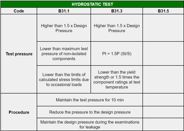
Hydrostatic Test
- Test fluid: The fluid shall be water unless there is the possibility of damage due to freezing or to adverse effects of water on the piping or the process. In that case, another non-toxic liquid may be used.
- Provision of air vents at high points: Vents shall be provided at high points of the piping system to purge air pockets while system is filling.
- Pressure and procedure: The pressure limits are different for ASME B31.1 and ASME B31.3.
ASME B31.1 Test Power Piping
The hydrostatic test pressure at any point in the piping system shall not be less than 1.5 times the design pressure, but shall not exceed the maximum allowable test pressure of any non-isolated component, nor shall it exceed the limits of calculated stresses due to occasional loads.
ASME B31.3 Test Process Piping
The test pressure shall be not less than 1.5 times the design pressure. When the design temperature is greater than the test temperature, the minimum pressure shall be calculated by eq. P T = 1,5P S T/S , where =allowable stress at test temperature, S=allowable stress at component design temperature, P=design gage pressure. The test pressure may be reduced to the maximum pressure that will not exceed the lower of the yield strength or 1.5 times the component ratings at test temperature. The pressure shall be continuously maintained for a minimum time of 10 minutes and may then be reduced to the design pressure and held for such time as may be necessary to conduct the examinations for leakage. Examinations for leakage shall be made of all joints and connections.
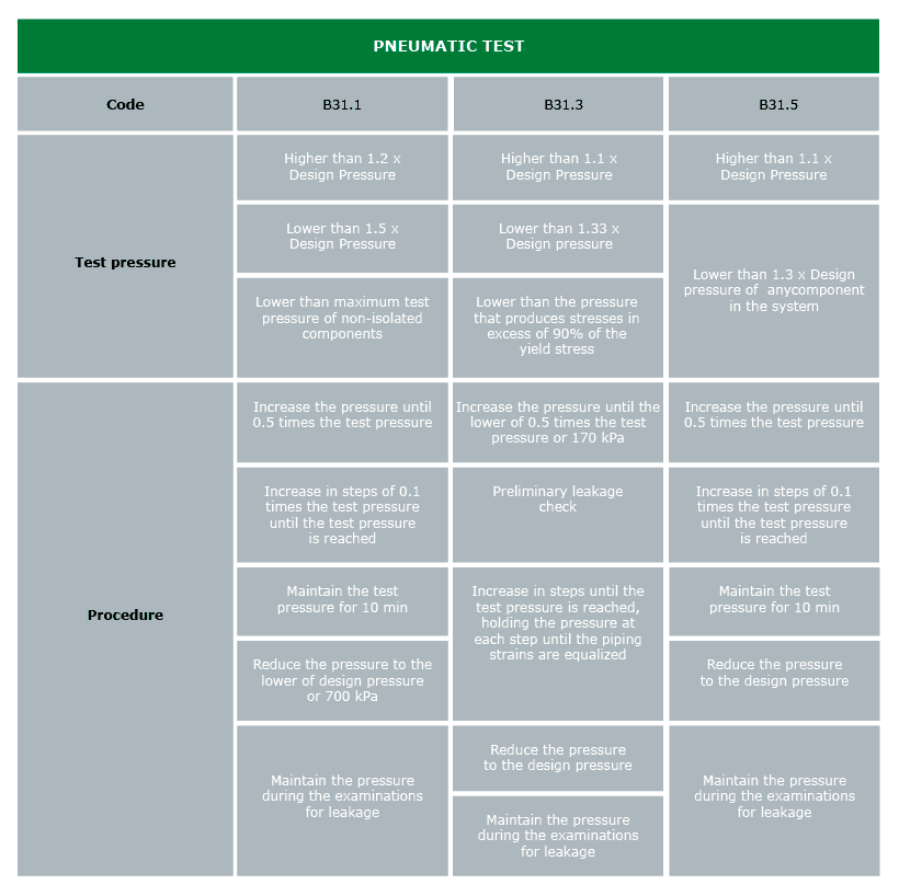
Pneumatic Test
- Precautions: Pneumatic testing involves the hazard of released energy stored in compressed gas. Particular care must be taken. It is recommended to be used only when piping systems are so designed that they cannot be filled with water, i.e, refrigerant systems; or when piping systems are to be used in services where traces of the testing medium cannot be tolerated.
- Test fluid: The gas used as test fluid, if not air, shall be nonflammable and nontoxic, such as nitrogen.
- Pressure and procedure: the pressure limits and methodology is different for the codes mentioned above.
ASME B3.1 Test Power Piping
The pneumatic test pressure shall not be less than 1.2 nor more than 1.5 times the design pressure of the piping system. It shall not exceed the maximum allowable test pressure of any non-isolated component. The pressure in the system shall gradually be increased to not more than 1/2 of the test pressure, after which the pressure shall be increased in steps of approximately 1/10 of the test pressure until the required test pressure is reached. The pressure shall be continuously maintained for a minimum time of 10 min. It shall then be reduced to the lower of design pressure or 100 psig [700 kPa (gage)] and held for such time as may be necessary to conduct the examination for leakage. Examination for leakage by soap bubble or equivalent method shall be made of all joints and connections.
ASME B31.3 Test Process Piping
The test pressure shall not be less than 1.1 times the design pressure and shall not exceed the lower of 1.33 times the design pressure or the pressure that would produce a nominal pressure stress or longitudinal stress in excess of 90 % of the yield stress of any component at the test temperature. The pressure shall be increased until a gage pressure, which is the lower of 0.5 times the test pressure or 170 kPa (25 psi), at which time a preliminary check shall be made. Thereafter, the pressure shall be gradually increased in steps until the pressure is reached, holding the pressure at each step until the piping strains are equalized. The pressure shall then be reduced to the design pressure before examining for leakage. During the test, a pressure relief device shall be provided, having a set pressure not higher than the test pressure plus the lower of 345 kPa (50 psi) or 10% of the test pressure.
It might interest you: Industrial refrigeration maintenance: best performance
ASME B31.5 Test Refrigeration Piping
The test pressure shall be at least 1.1 and shall not exceed 1.3 times the design pressure of any component in the system. The pressure in the system shall be gradually increased to 0.5 times the test pressure, after which the pressure shall be increased in steps of approximately 1/10 of the test pressure until the required test pressure is reached. The test pressure shall be maintained for at least 10 minutes. It may then be reduced to the design pressure and conduct the examination for leakage. During the test, a pressure relief device shall be provided, having a set pressure above the test pressure, but low enough to prevent permanent deformation of any of the system components.
What are the benefits with outsourcing pressure testing?
Working with a company that specializes in heating and cooling services, maintenance and testing is often more beneficial than integrating dedicated personnel inhouse, reducing cost, time, and resources.
Other benefits of outsourcing a pressure test include:
- Faster turnaround time
- Increased safety for your staff
- mproved product quality assurance
- Decreasing repair costs
- Minimizing risk exposure and liability claims.
Discover: Benefits of District Energy: advantages of heating Heating & Cooling District
Why is it important to do a pressure test with asme procedure?
Pressure tests carried out according to the asme procedure allow us to guarantee the correct performance of the system and to detect that there are no leaks and that the installation is robust.
That is why it is important to consider specialised district energy contractors such as Araner. It is essential to work with top-notch, quality-oriented professionals to ensure the safety of the plant.
ARANER, the industrial cooling engineering experts
We are experts in designing, manufacturing and installing tailor-made industrial cooling solutions with a positive economic impact. We have worked worldwide in the development of Turbine Inlet Air Cooling, District Cooling and Thermal Energy Storage. Get in touch with our experts if you are interested in any of our solutions or if you need technical advice. We will be glad to help!