The electrical system design of a cooling plant is deeply influenced by its final application. We can find a wide range of cooling applications in different industrial sectors in which cooling plays a vital role: Power generation, Oil & Gas, Data Centers, Medical facilities, Chemical plants… In such cases, the design specification for the main electrical equipment will be affected in terms of number of items, technical parameters, performance requirement, etc… Most of these applications will demand full availability of the system even under fault conditions, where the system is expected to provide full service continuity without any electrical interruption. Under these circumstances, there is a need of a solid reliable electrical system with components that can operate under the most demanding conditions, sometimes even out of the initial design parameters (i.e. overloading of transformers and induction motors).
In order to have a fail-safe electrical design, one of the options would be to provide the system with a certain redundancy capacity in the equipment, according to project demand. Depending on the redundancy philosophy, this will result in a duplication of the equipment most susceptible to fail. It is now ensured that the system can bear the fault of main equipment without major interruption times. But the service continuity without interruption will be direct linked with the switching technique to change from the faulty equipment to the healthy one. To overcome this problem, a typical arrangement used in MV Switchgears, is the Automatic Transfer Switch (ATS). Normally it will be a combination of numerical protection relays (IED) with synchro-check function (25) and two —or three— circuit breaker (CB) configuration. These CBs will act in coordination to isolate the selected source and restore the energy in the system. The ATS will switch between duty/stand-by energy sources in order to provide service continuity ensuring that the sources are synchronized.
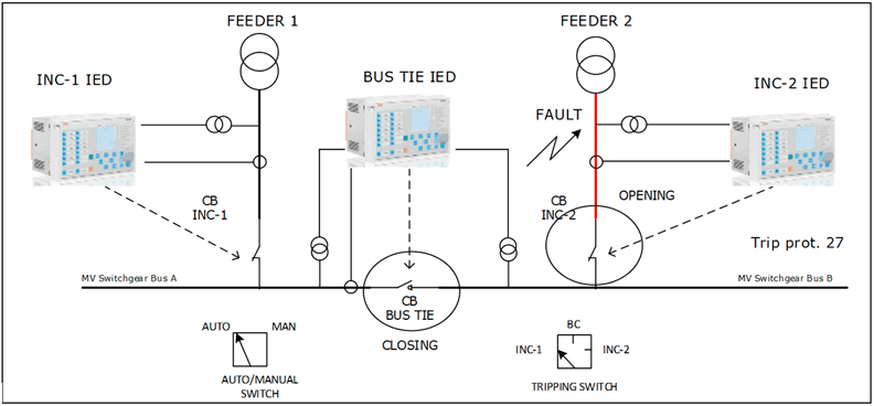
Figure 1: Typical ATS configuration using 3 CBs and ABB IEDs showing fault in one of the feeders
The equipment feeding the plant (i.e. transformers, cables, CBs), shall be of course oversized and adapted to the plant redundancy capacity (i.e. 2 transformers 100 % load capacity each).
ATS Operation
A standard ATS can be initiated in manual and automatic.
- In case of manual operation, there is a deliberate switching between two sources (both healthy) and a voltage synchronization takes place, then the selected source is isolated in a bumpless transfer.
- In automatic mode, the system will first detect the under voltage according to set value, opening the respective CB and then closing the alternative source CB to restore voltage.
The standard ATS can be slow for certain applications and may not avoid service interruption in case of fault (in auto mode). It detects the under voltage with certain delay and there is no voltage synchronization between sources (2 out of 3 philosophy). It achieves transfer times longer than 10 cycles (200 msec) and phase angle difference of more than 90º, which is the definition of a fast transfer based on general experience. This could be potentially harmful for plants with Induction Motors where a restart with residual voltage after certain time limit will cause high starting currents, which could result in system voltage drops or motor winding damage. The main guidelines to check the transient impact of transfer in motors are included in ANSI C50.41-2012. For very critical processes, there is another alternative known as High Speed Transfer System (HSTS) or High Speed Bus Transfer (HSBT). The HSBT provides a reliable and real time fast transfer achieving transfer times in the range of 1-1.5 cycles (20-30 msec) avoiding power interruption.
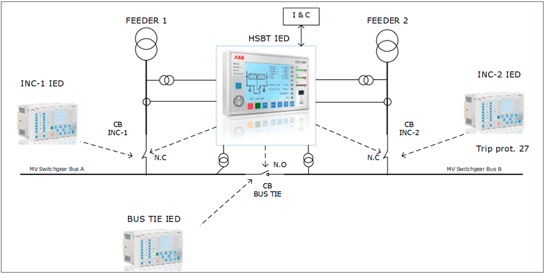
Figure 2: Typical HSBT configuration using 3 CBs ABB IED for feeder protection and bus transfer management
HSBT operation
The HSBT system is based on micro-processor controlled intelligent devices, reading analog signals for voltage and current. While a micro controller executes the logical processes in communication with binary input/output devices. There are different transfer modes depending on the nature of the process, nature of the loads involved and network interrelation in the instant of initiation of the transfer. In general, the transfer modes are the following:
- Fast Transfer
- Transfer at the 1st phase coincidence
- Residual voltage transfer
- Time-operated transfer
The optimum, fastest and preferred mode is the fast transfer mode which happens when the main and stand-by source are synchronized within specified limit values. In this mode, the first operation is closing the stand-by CB and then opening the faulty source to be isolated. The transfer is seamless and follows the make-before-break philosophy. The time is completely dependent on the operating time of the CBs concerned. For this reason, in HSBT systems CBs are commonly equipped with faster and more accurate magnetic actuator replacing the slower spring based operating mechanism.
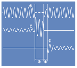
Figure 3: Fast Transfer (source ABB: High Speed Transfer Device SUE3000)
- Bus bar Voltage
- Current in feeder 1
- Current in feeder 2
- Trip time
- Dead time
In the transfer mode at the 1st phase coincidence, there is a momentary loss of supply due to the fact that there are no synchronizing conditions and no fast transfer is carried out. The first operation is to open one CB immediately and the second CB is closed once the difference between stand-by and bus voltage reach the first minimum phase angle. The HSBT controller predicts and anticipates the point of the 1 st phase coincidence, so it compensates the delays of the actual installation processing times. The close command is issued before the actual 1 st minimum of the difference of voltages occurs in terms of phase angle
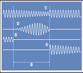
Figure 4: Transfer with 1 st phase coincidence ( source ABB: High Speed Transfer Device SUE3000): Transfer with 1st phase coincidence (source ABB: High Speed Transfer Device SUE3000)
- Bus bar Voltage
- Difference voltage between stand-by and bus bar voltage
- Main feeder current
- Stand-by feeder current
- Transfer duration
In the rest of the transfer modes, the transfer parameters are manually set and it takes place when certain voltage level is reached in the bus bar or at a specific time.
Full availability and no unexpected surprises with ARANER
In conclusion, the electrical system availability is directly dependent on the application and the consequences that a blackout might have in the affected process or customers. There are certain processes where increasing the service availability turns out direct into cost savings and the investment is recovered in a relative short term. In a practical way, one successful transfer that avoids service interruption of a plant and saves on costly starting processes can represent the complete pay back of the initial investment cost of the ATS or HSBT system. Our experts can help you to guarantee full availability, based on your specific requirements. Contact ARANER for more information. If you enjoyed this post, you may be want to know different heat rejection condensing technologies.