The Vapor Compression Refrigeration Cycle is nearly 200 years old, but it does not seem ready to leave the scene any time soon. While some people have viewed this method as environmentally harmful and inefficient, the cycle is still applicable in the industrial sphere. Natural gas plants, petroleum refineries, and petrochemical plants and most of the food and beverage processes are some of the industrial plants that utilize vapor compression refrigeration systems. What is its defining feature of these systems? The simplest explanation of this system is a heat engine working in reverse, technically referred to as reverse Carnot engine. In other words, it is the transfer of heat from a cold reservoir to a hot one. Clausius Statement of the Second Law of thermodynamics states: “It is impossible to construct a device that operates in a cycle and produces no effect other than the transfer of heat from a lower-temperature body to a higher-temperature body”. Since the vapor compression cycle is against the Second Law of Thermodynamics, some work is necessary for the transfer to take place.
Why Do We Use The Term “Compression”?
The Vapor Compression Refrigeration Cycle involves four components: compressor, condenser, expansion valve/throttle valve and evaporator. It is a compression process, whose aim is to raise the refrigerant pressure, as it flows from an evaporator. The high-pressure refrigerant flows through a condenser/heat exchanger before attaining the initial low pressure and going back to the evaporator. A more detailed explanation of the steps is as explained below.
Step 1: Compression
The refrigerant (for example R-717) enters the compressor at low temperature and low pressure. It is in a gaseous state. Here, compression takes place to raise the temperature and refrigerant pressure. The refrigerant leaves the compressor and enters to the condenser. Since this process requires work, an electric motor may be used. Compressors themselves can be scroll, screw, centrifugal or reciprocating types.
Step 2: Condensation
The condenser is essentially a heat exchanger. Heat is transferred from the refrigerant to a flow of water. This water goes to a cooling tower for cooling in the case of water-cooled condensation. Note that seawater and air-cooling methods may also play this role. As the refrigerant flows through the condenser, it is in a constant pressure. One cannot afford to ignore condenser safety and performance. Specifically, pressure control is paramount for safety and efficiency reasons. There are several pressure-controlling devices to take care of this requirement
Step 3: Throttling and Expansion
When the refrigerant enters the throttling valve, it expands and releases pressure. Consequently, the temperature drops at this stage. Because of these changes, the refrigerant leaves the throttle valve as a liquid vapor mixture, typically in proportions of around 75 % and 25 % respectively. Throttling valves play two crucial roles in the vapor compression cycle. First, they maintain a pressure differential between low- and high-pressure sides. Second, they control the amount of liquid refrigerant entering the evaporator.
Step 4: Evaporation
At this stage of the Vapor Compression Refrigeration Cycle, the refrigerant is at a lower temperature than its surroundings. Therefore, it evaporates and absorbs latent heat of vaporization. Heat extraction from the refrigerant happens at low pressure and temperature. Compressor suction effect helps maintain the low pressure. There are different evaporator versions in the market, but the major classifications are liquid cooling and air cooling, depending whether they cool liquid or air respectively.
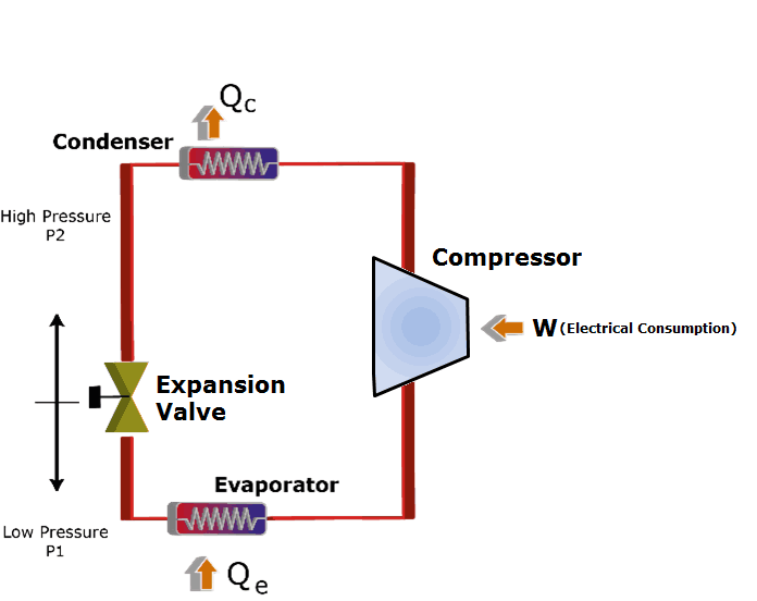
Fig 1: Schematic Representation of the Steps
Problems in the Vapor Compression Cycle
The Coefficient of Performance (COP) expresses the efficiency of this cycle. Knowing that the aim of the refrigerator is heat removal and that this process requires work, the COP of the cycle becomes: Where “h” is the enthalpy in the system. Some of the Vapor Compression Refrigeration Cycle Problems that may affect this value are:
Compressor Leakage/Failure
The failure of an industrial refrigeration compressor can be expensive affair to the company and damaging to the manufacturer’s reputation. Often, manufacturers will tear down returned compressors in search faults. Over years of studies, some common reasons for compressor failure have been identified to include lubrication problems, overheating, slugging, flood back and contamination.
Fouling – Evaporator and Condenser
Fouling is any insulator hinders transfer between the water and the refrigerant. It could result from algae growth, sedimentation, scale formation or slime. As this problem increases head pressure, it can lead to increased energy use by the compressor. What is the best practice? Keep the evaporator surface and condenser tubes clean. Water treatment practices need to be on point to keep this problem at bay.
Motor Cooling
The motor is easily the highest energy consumer in the vapor compression cycle. Most times when efficiency drops in this device, it is because of a cooling problem. Many issues could lead to this- blocked air filters, dirty air passages etc. Regular checks of the chiller logs should unearth any anomaly, specifically the comparison between amperage and voltage.
Liquid Line Restriction
If you are a refrigeration technician and you encounter low evaporator pressure, one of the areas to check is the liquid line, specifically for any form of restriction. Many other symptoms could point to the problem that affects the system enthalpy as shown by the following examples:
- Abnormally high discharge temperature
- Low current draw
- High superheats
- Low condensing pressures
- Local frost close to the restriction
- Bubbles in sight glass
In commercial cooling, liquid line restriction can degrade cooling capacity of the system by as much as 50%. Diagnosis of this problem does not to be fancy, as an experienced technician can tell something is not okay by just checking the system history or checking visually. If you are not acquainted with the system, you may need to conduct a few tests to pinpoint the issue. The first one is temperature drop test, which is done at all points likely to develop restriction. You could also perform a freeze test if finding the exact point becomes troublesome. This test comes in handy when you suspect several components such as evaporator, feeder tubes and metering device. Thermal imaging has to be the most advanced and reliable method of identifying liquid line restriction. It gives real time results that help you identify the problem as shown by temperature changes.
Need To Improve Your System?
Understanding the vapor compression cycle is a critical step towards countering common industrial refrigeration problems. All the components involved in the cycle have the potential to disrupt efficiency or overall functionality of the system altogether. ARANER can help you identify upgrading opportunities within your Vapor Compression Refrigeration Cycle. The process involves evaluation of the current system condition and the possible improvement opportunities. Other possible improvement approaches for your system include installation of high efficiency system components cooling tower upgrades. Contact the team today for these and other industrial refrigeration solutions.