In stratified Thermal Energy Storage (TES) tanks, the thermocline refers to the transition or mixing layer that forms between the warmer surface water and colder water that occurs deeper. Thermocline layers occur naturally, separating the water by temperature and density. A thermocline layer is characterized by a radical drop in temperature given that the gradient from the mixed layer to the deeper, denser colder layers of water is steep.
The thermocline layer in a body of water, a lake, or the ocean varies with the air and water temperatures. In a TES tank, the thermocline layer is more consistent with the cycling of the tank but still plays a vital role. Using thermocline technology for TES allows a single tank to store both charged and discharged cooling water. Low entrance velocities and natural buoyancy forces help to maintain the thermal stratification of the tank; essentially, the hot water "floats" while cold water "sinks." Below, we discuss in greater detail the thermocline.
The Thermocline and Thermal Efficiency
There are three layers in a thermocline within a TES tank that allow the system to operate effectively and efficiently from a single tank. The top layer consists of warmer, less dense water. Colder, less dense water makes up the bottom layer and in the middle is the thermocline. The thermocline layer moves up or down with the charging cycle of the tank. Click here to see a short video demonstration of this practice in action.
The thickness of the thermocline layer is a direct indicator of the level of mixing occurring in the tank. Mixing occurs mainly as the result of influent flow velocity within the tank. The less mixing that occurs, the smaller the thermocline layer and the more efficient the system. High velocity inflow of water to the tank or other operating variations may disturb the stratification within the tank disrupting the thermocline and decreasing efficiency.
Thermocline Layer Adjustments
TES tanks include baffles to adjust the flow rate inside the tank, limiting velocity and encouraging the development of the thermocline layer. However, other operational considerations may further encourage developing an efficient thermocline layer, including:
- Reducing heat losses, including heat conduction through the tank walls
- Maintaining minimal flow rates through the tank.
- Directing flow in the tank, so it is somewhat parallel to the sides of the tank
- Regularly discharging the tank fully
The thermocline layer naturally expands when chilled water leaves the tank and discharged warm water returns, becoming less efficient as it expands. Typically, to restore the thermocline layer flow through the tank would need to be stopped allowing the non-turbulent water to re-stratify. However, re-stratification can be encouraged while the tank is in operation by drawing water from the thermocline region of the tank. This method not only encourages re-stratification but also may help to prevent eutrophication and reduce or even eliminate the need for flushing the tank.
The Thermocline in Action
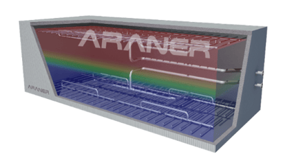 Figure 1: The thermocline layer in a rectangular TES Tank.
Thermal Energy Storage takes advantage of off-peak rates during peak hours and helps to balance supply and demand within the system, ultimately reducing costs and increasing efficiency. How does this process work exactly? We build a carefully designed, well-insulated tank filled with chilled water from the cooling plant through the bottom diffuser. At the end of a distribution cycle, the TES tank should be full of primarily warm water, and the thermocline layer close to the bottom of the tank. During off-peak hours, warm water is removed from the top of the tank through the diffuser and sent to the chiller plant. The chilled water refills the tank again through the bottom diffuser; once fully charged, the thermocline layer is at the top of the tank. The capital cost savings provided by using a single storage tank system with a thermocline layer over a two-tank system are typically 20-35% when the needs and conditions of the project allow it. A thermocline tank does need to be larger, but because only one tank is required, it is cheaper to install. Also, the piping may be more straight-forward with a thermocline tank.
Heat Transfer
Thermal efficiency remains highest in an adiabatic tank where there is no thermal transfer through the walls of the tank. Tank design becomes an essential consideration for thermocline to work correctly. Everything from proper tank insulation to tank height can affect tank efficiency. Computational fluid dynamics is used to optimize the design parameters of the tank. This same analysis can also be used to observe how different variables affect the thermocline. The other variables analyzed pipe sizes, velocity, flow direction, Reynolds number and the aspect ratio of the tank.
Conclusion
Stratified Thermal Energy Storage with thermocline is a cost-effective way to level out demands, improve efficiency, and transfer costs to off-peak production times. Are you thinking about adding a TES tank to your next project? ARANER has decades of experience with Thermal Energy Storage tanks and the thermocline. We are always keeping up with the latest in the design and operation of thermal energy storage tanks with a thermocline layer. Let us help you decide how thermocline can work for you.