All pressurized piping systems inevitably experience transient effects, whether due to normal or emergency events. Specifically, rapid flow changes during transient events generate propagating pressure waves which have both positive and negative phases, also referred to as water hammer, or in a generic way: liquid hammer. Liquid hammer can have not only serious and even devastating consequences on hydraulic systems but also risks for operators, including disruption of normal control setting, fatigue and stretch of the pipe wall, separation at bends, and pipe rupture. More dramatically, these pressure waves may lead to a complete equipment failure if the cavitating flow is triggered.
Figure 1: Industrial Piping System
At ARANER, we specialize in the analysis, design, and implementation of industrial piping systems, as well as District Cooling and Heating technologies. Our engineers and expert design team have years of experience with Liquid Hammer and all types of industrial systems, and thus know the best way to approach your next project. In this blog post, based upon ARANER’s wealth of expertise, you will discover the main causes affecting liquid hammer, simplified liquid hammer calculations, liquid hammer control strategies, and liquid hammer in District Cooling and Heating.

Causes Affecting Liquid Hammer
Envision a piping system within which the flow of liquid is suddenly stopped; the liquid tries to continue in the same direction. In the area where the velocity change occurs, the liquid pressure increases dramatically, due to the momentum force. As it rebounds, it increases the pressure in the region near it and forms an acoustic pressure wave. This pressure wave travels downstream the pipe at the speed of sound in the liquid. The acoustic wave will be reflected when it encounters an obstruction, such as a pump, fitting, or valve. The closure or opening of a valve in a system is one of the most common cause of liquid hammer. The amount of pressure difference, combined, with the initial pressure, largely depends on the closing (opening) characteristic of the valve. In practice, the closing characteristics of valves or check valves are optimized so that some 80% of the cross-sectional area is closed relatively quickly, while the remaining 20% of the area slowly reduces the mass flow by means of damping facilities, in order to avoid excessive pressure peaks. Liquid hammer occurs not only during valve operations but also in connection with abnormal conditions such as pump failure or pipe rupture, with subsequent sealing of the broken pipe by the closing of a valve. Here the piping system is exposed to double loading:
- The first load results from the pressure waves which start at the failing pump or run into the system from the point of rupture.
- The other one, results from the subsequent opening and closing of valves and check valves.
It is interesting to note that liquid hammer is of greater significance in low head pumping systems than in high head systems. For a given head rise would be a larger proportion of the pumping head in a low head pumping system than in a high head system. Additional factors that either influence the severity or perhaps even cause liquid hammer include check valve action, product wave velocity, pipe size, number of pumps operating, and even the flywheel effect of pump impellers.
Simplified Liquid Hammer Calculations
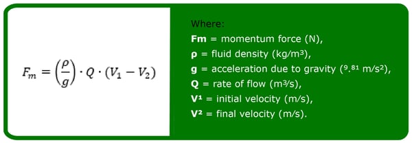
Simplified liquid hammer calculations can be used to indicate if liquid hammer is severe. The potential magnitude is dependent on the speed of valve closure and the liquid velocity in the pipe prior to the start of valve closure. If the speed of the valve closure, in seconds, is greater than the total length of pipe (L), in m, divided by 1000, then momentum theory (Newton's second law of motion) applies:
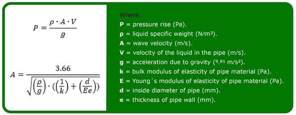
On the other hand, if the time to close the valve is less than L/1,000 s, then the acoustic shock wave/elastic column theory applies, governed by the following equation:
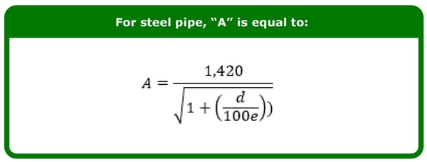
As an example, if we assume the liquid is water flowing in rigid steel pipe at ambient temperature, the pipe diameter is 600 mm, the wall thickness is 5 mm, the wave velocity is 957.4 m/s, and the liquid is traveling at the maximum recommended discharge velocity of 4.6 m/s, the instantaneous pressure inside the casing would jump to 4,480 kPa. Pump casings are not usually designed for this magnitude of pressure, especially if the casing is made of a brittle material, such as cast iron. Even if the casing is constructed of a more ductile material, the shock wave may still cause the permanent deformation of some components and, ultimately, fail.
Liquid Hammer Control Strategies
The best design measure is, of course, to completely avoid liquid hammer and transient forces. This means that in a piping system the fluid must not accelerate or decelerate suddenly. However, the operation of any industrial plant may undergo such unavoidable conditions as a result of disturbances in the system. In order to address liquid hammer prevention, large variety of transient control strategies are commonly employed; such as improvements within the distribution system (e.g.: pipe diameter or profile, wall thickness, alignment and other hydraulic components), damping strategies, optimal operational procedures and dedicated device installation (e.g.: automatic control valves, air chambers). When assessing the liquid hammer occurring in piping there are design and operating measures to reduce the slope of pressure ramp and mitigate the resulting loads. As regards valve operations, the closing (and opening) characteristics can be optimized so that the liquid hammer occurring is kept within tolerable limits while the setting times remain short enough to warrant safe operation. After initial rapid closing the damping mechanism of the valves is activated and then causes slow closing up to complete shut off. The pressure wave periodically moves to and fro between pipe and the valve, with decreasing pressure amplitude. In case of pump failures, the loads on the piping system can be reduced by increasing the flywheel effects of the pumps. The longer it takes the pump to slow down, the slower pump slows down and liquid decelerates, then the smaller the amplitudes of pressure waves will be. In special cases, such as heavy fluids, specific procedures are recommended to provide sufficient flow cross section in a pump, even if the pump fails. In the ease of pumps which are arranged in parallel it is usual to install a non-return check valve in order to avoid return flows. This automatic closing element can also be the starting point of marked pressure waves. Such check valves are normally equipped with adjustable damping mechanisms which are set so that they neither close too abruptly nor run the risk of opening and closing several times. From a design perspective, typical practices make use of a combination of various design strategies to soften liquid hammer waves at sensitive locations of the hydraulic system; however, these practices may actually worsen a system transient response due to substantial inconsistency between the embedded multiple devices. One of the most successful measures for liquid hammer control with low wave speed is the inline strategy, which consists in replacing a short section of the sensitive zone of the existing steel piping system by another made of high or low density polyethylene pipe wall material (i.e., HDPE or LDPE). Such a design strategy could successfully be employed to mitigate excessive piezometric head rise and drop. Furthermore, the liquid hammer can also determine the materials to be selected and in addition it may need the use of certain types of supports, without mentioning the sizing of the piping so that it is sufficient for the liquid hammer. In summary, liquid hammer can be controlled through proper valve closure rates (with slow closing valves), the addition of diaphragm tanks or similar accumulators to absorb the pressure wave, relief valves to release the pressure, and an inline strategy.
Liquid Hammer in District Cooling and Heating Systems
Generally liquid hammer can occur in any thermal–hydraulic systems such as District Cooling and Heating plants, and it is extremely dangerous for its performance since, if the high pressure peaks exceeds the pressure range of a pipe or equipment given by the manufacturer, it can affect the pipeline integrity. The high-pressure peaks in District Cooling or District Heating depend on:
- Initial liquid velocity before closing the check valve.
- Steam appearing due to cavitation, and steam collapsing.
- Valve induced liquid hammer.
- Void induced liquid hammer.
- Condensation induced liquid hammer.
 Figure 2: Piping systems in a District Cooling Plant
The cases, when the liquid hammers occurred in the pipeline systems as the consequences of standard actions such as start up or shut down of systems and components, opening or closure of valves, switch over from one component (e.g. pump, heat exchanger) to another, belong to the first type of liquid hammer. The most severe liquid hammers in District Cooling and Heating plants may be caused due to rapid closure of isolation valve. Pressure pulses in the presence of liquid and vapor (for example when there is a two-phase flow) can lead to rapid condensation of the vapor, leading to the commonly known as condensation induced liquid hammer. There are several reasons for the formation of large cavities or steam bubbles in pipelines. For liquid flow the pressure at some sections of the pipes may be reduced below the saturation pressure when a rarefaction wave occurs or the liquid column is separated. Liquid may vaporize and dissolved gas may separate from the liquid at the lowered pressure to form a cavity. These conditions may occur when an upstream pump suddenly stops or a valve suddenly closes. In case of blackout accident in a pump station, the pressure peak due to liquid hammer is predicted to be lower than the hydraulic test pressure limit. Even when the conditions were set to the most unfavorable scenario (check valve closes at highest liquid velocity through the valve), it took to assume different physical system configuration to reach the hydraulic test pressure limit.
Conclusion
All piping systems are exposed to suffer liquid hammer due to fast open or closure of the valves, or even during pump failure or sealing operations after equipment rupture. Additional factors that either influence the severity or perhaps even cause liquid hammer include check valve action, product wave velocity, pipe size, number of pumps operating, and even the flywheel effect of pump impellers. To address the liquid hammer prevention, a large variety of transient control strategies are commonly employed:
- Valves opening and closing optimized characteristics
- Check valves with damping mechanism
- Flywheels in pumps
- Material and/or size of pipes
- For low pressure systems a short pipe of plastic material
- Relief valves
- Expansion tanks.
In District Cooling and Heating systems, apart from the liquid hammer problems mentioned above, there is a risk of liquid hammer due to steam bubble collapse. This kind of liquid hammer is generated due to the presence of liquid and vapor trapped in a portion of horizontal steam piping and they can lead to rapid condensation of the vapor. These conditions may occur when an upstream pump suddenly stops or a valve suddenly closes. The best way to combat liquid hammer in your industrial piping systems is to have a tailor-made design for your plant and its components. ARANER’s engineers and design team specialize in the analysis, planning, and implementation of District Cooling and Heating technologies. Get to know our team! To discover ARANER’s expertise, as well as the best planning and design methods for your next District Energy project, read our free expert eBook.