Thermal Energy Storage (TES) are accumulators that store the available thermal energy to be used in a later stage. Its application to Cooling & Heating Plants provides many advantages when the energy demand is fluctuating:
- Maximum efficiency in chilled water production and consumption.
- Smaller refrigeration equipment sizes and costs.
- Energy production and storage during electricity low-cost periods.
- Reduces annual energy and operational cost.
- Provide owners with significant financial benefits.
These benefits and the high efficiency of stratified thermal energy storage have converted them into a robust and worldwide implemented technology.
Moreover, TES are a very flexible energy storage system since they have multiple applications that result in different possibilities of installation. The most common arrangements for the installation of TES tanks are: above-ground, underground or partially buried TES tanks.
Flexible Implantation of TES Tanks: Above-ground
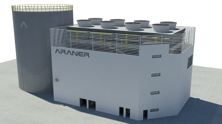
One of the most common arrangements of TES tanks is above ground. The installation of above-ground storage is normally carried out through cylindrical welded steel tanks. The extended implementation of above-ground tanks streamlines its design and construction. This configuration is also characterized by reduced maintenance.
When the architectural environment and the visual impact is a fundamental aspect, creative landscaping, surface texture, cladding, color and even lighting, implementing this flexible energy storage system aboveground can be applied.
Flexible Implantation of TES Tanks: Under-ground
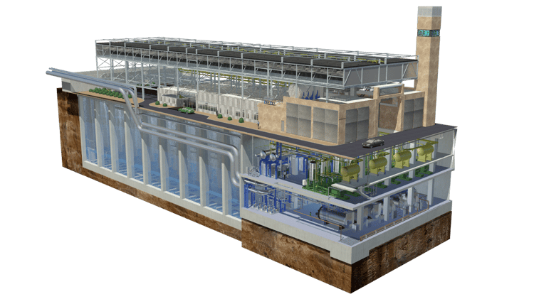
In many circumstances, district cooling plants are intrinsically planned as part of the city and located in the downtown, where the availability of space is limited. In those cases where the footprint is limited, TES tanks provide a flexible energy storage solution that can be constructed in basements of buildings.
Although basements can involve reduced heights and sometimes intricate geometries with columns and corners, an accurate design of diffusers can counteract these challenging requirements. Underground thermal storages also represent a good approach for long-timeframes applications.
The TES tank of Jordan District Cooling Plant with its 70,000 m3 capacity represents an exceptional example of underground tanks. More information can be found in Abdali Boulevard Jordan District Cooling Case Study.
A mixed solution with TES: Partially buried tanks
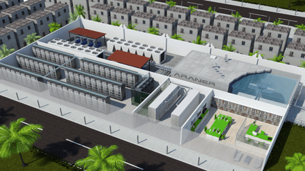 A compromise solution between aboveground and underground arrangements is partially buried tanks. In some cases, building areas are subject to height limitations and the excavation of a part of the required tank height can lead to meet the regulations and requirements.
In this case, the flexibility of thermal energy storage tanks offers another alternative to maximize efficiency with minimal equipment.
The partially buried tank of Al Ashghal Data Center (Qatar), with 2.5 m height buried and 2.5 m height aboveground, represents an example of this approach. More information can be found in Al Ashghal Data Center Case Study.