Harmonic distortion is a sort of “pollution” in the electric supply that can cause problems if the voltage distribution caused by harmonic currents increases above certain limits. The growing use of non-linear loads such as converters with power electronics and the on/off-switching effects in power consumers is increasing harmonics generation in the consumer installations that involves the appearance of disturbances in the supply. This could be the case of Cooling Plants where this type of loads are widespread, therefore it is very important being able to identify the harmonic distortion phenomena, being aware of his effects and providing solutions to prevent them. First of all, for the study of the harmonics there are some concepts which need to be taken into account: - Fundamental harmonic: The harmonics are the components of a distorted waveform and their use allows to analyze any non-sinusoidal periodic waveform by decomposing it into several sinusoidal components. The harmonic with the frequency corresponding to the period of the original waveform is called fundamental harmonic.
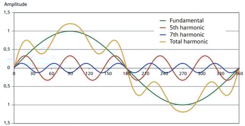
Figure 1: Harmonics wave form (Source: Siemens)
- Individual harmonic: The individual harmonic component is defined as the percentage of harmonics for order h with respect to the fundamental: 
In a Cooling Plant the main source of harmonics are 3-phase nonlinear loads (VFDs, UPS, converters…), where the dominant harmonic orders are 5th, 7th, 11th and 13th. The mentioned equipment usually come with six-pulse converters with a harmonic spectrum similar to the one shown in Figure 2 below.
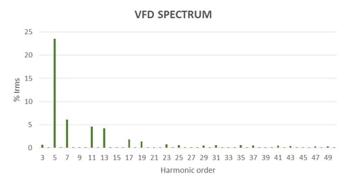
Figure 2: VFD Harmonic Distortion Spectrum
- Total harmonic distortion (THD): The Total Harmonic Distortion (voltage and current THD) is an indicator of the distortion of a signal. 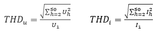
- Point of common coupling (PCC): It is the point at which the harmonic distortion is specified, it is the connection between the plant and the utility network.

Which harmful effects can cause harmonic distortions in our plant?
Harmonic distortion can produce undesirable effects in protection relays and circuit breaker (among other equipment), for instance high distortion levels can make the circuit breakers to trip under normal conditions. If these unintended trips appear in the incomer circuit breaker this issue becomes critical, as there could be a blackout in the plant. Wherever harmonics are present in a system, resonance phenomena can appear in case power factor correction capacitors are used in combination with non-linear loads. Harmonic resonance results in very high harmonic currents and voltages at the resonant frequency that can lead to the destruction of the capacitors. Harmonic distortion also generates electromagnetic disturbances that can affect the electronic devices or measurement equipment which may cause malfunction or even irreparable damages. Also, high levels of harmonic distortion decrease the power factor. This is due to a new component of power as consequence of harmonic currents, named Harmonic Distortion power ( D). Therefore all the inconveniences related to a low power factor needs to be considered. New power factor is defined as per below formula:
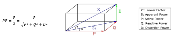
Figure 3: Power diagram
Some of the negative consequences that harmonics can have on typical equipment found in a Cooling Plant are summarized in below table:
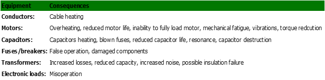
In addition to mentioned disadvantages, more and more utilities are demanding their customers more strict requirements related to harmonic distortion. IEEE Standard 519-1992, IEEE Recommended Practices and Requirements for Harmonic Control in Electrical Power Systems, represents the most recent effort to establish a standard level of acceptable harmonic distortion levels on a power system. End users must limit the harmonic currents injected to the PCC, and the utility must control the harmonic distortion. Both individual harmonics and THD have their own limit that must not be exceeded. These limits depend on different parameters such as voltage level, rated current and shortcircuit current, which are defined in IEEE Standard 519-1992.
Possible solutions to decrease harmonic levels
In order to comply with harmonic distortion requirements and prevent the harmful effects in the cooling plant, some of the solutions shown below can be applied: - Converters with lower harmonics contents Install more efficient multipulse converters with lower harmonics levels (12-pulse, 18-pulse…). These type of converters are more expensive than 6-pulse and have larger footprint as they are equipped with phase shifting transformers. As a result, they prevent the plant designer from installing new equipment like harmonic filters.
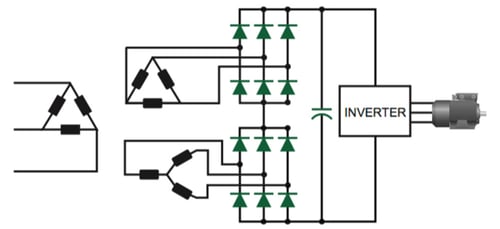
Figure 4: 12-pulse converter
- Active Front End VFDs (with active rectifier): These are similar to multipulse converter equipment, but the same use IGBTs at the rectifier to convert AC power to DC and the switching is controlled electronically. It can reduce the input current waveform THD below 5%. These items reduce the footprint but the generated heat is increased, thus requiring additional room cooling. This would be a proper solution when the available space in the electrical room is small, but the cost is higher than multipulse equipment.
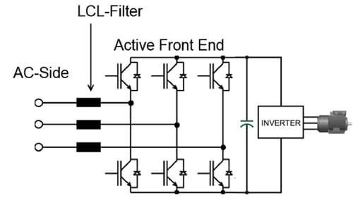
Figure 5: Active Front End VFD
- Passive filters: Passive filters consists of a capacitor and series reactor that are installed in series with nonlinear loads to absorb specific harmonic currents generated. This type of filters are cost-effective and easy to be connected and commissioned. They must be defined for specific cases, according to a particular harmonic to be filtered. Each passive filter is tuned for a certain frequency range, usually covering one specific harmonic order. Passive filters provide low flexibility in case that harmonic distortion conditions changes due to an extension of the plant, as they need to be modified to adequate to the new conditions of the plant. Also, as this type filters is installed in series with the load, an extra voltage drop is added to the circuit that needs to be taken into account in the design.
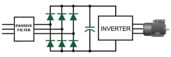
Figure 6: Passive Filter
- Active filters: The active filter uses power electronic switching to generate harmonic currents that cancel the harmonic currents of the system. They are installed in parallel with nonlinear loads to inject a counter phase current to harmonics current in our plant. These type of filters are more expensive and complex to be adjusted and commissioned. As advantages, they can automatically eliminate the current harmonics present in a network in a wide range of frequencies. They read the harmonics levels of the network and inject the required current to keep the THD value below programmed threshold, performing an accurate harmonic calculation to select a proper filter and set it according to requirements is very important. They can also be used as a power factor corrector when they are not working at full load (as this will reduce the harmonic limiting capacity) 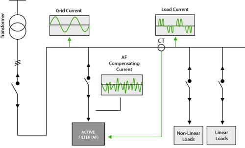
Figure 7: Active Filter Schematic
Conclusion
As shown in this post, the harmonic distortion is an actual problem in electrical systems that can trigger important negative consequences in our plant. This can become more critical since problems due to harmonic distortion can be no detectable at the beginning of the plant operation, but over the time they can get worse and can cause unnecessary interruptions in the plant production that can involve important extra costs. Also, harmonic distortion needs to comply with the electrical utilities requirements, so the most recommended engineering practice is to perform a harmonic study during the design stage to take the necessary corrective measures to achieve a harmonic distortion within the acceptable limits.